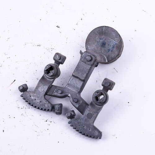
Every manufacturing method, including aluminum die casting, begins with a design. A particular method to assure optimal aluminum die-casting production efficiency is to perfect the manufacturing design process. As a result, we offer a guide that helps both manufacturers better understand the aluminum casting design process.
This article will provide you with valuable insight into the die-casting process, the role of DFM in the process, and useful tips for developing better aluminum casting parts. Read on to learn more about this great information.
Brief Overview of Aluminum Die Casting
Die casting has been a long-standing manufacturing technique in the industry due to its capacity to make parts and products with intricate parts and complicated geometry with great precision. Extreme pressure is used in the aluminum die-casting process to press molten metal into a mold cavity. This procedure takes place under extremely high pressure.
Die casting can be done using a variety of materials, although aluminum is still the most popular and best option. This is due to the fact that die-casting aluminum has greater advantages than other metals.
The following are additional advantages to using aluminum for die casting:
Simple to work with
Aluminum’s simplicity in casting is one of the main reasons, engineers prefer using it for die-casting parts and products. Engineers can produce a wide range of products thanks to its outstanding castability. Its resistance to heat and corrosion is an additional characteristic that makes working with it ease. This makes aluminum more able to tolerate higher operating temperatures than most materials.
Lightweight
Aluminum is one of the lightest metals. Aluminum is the best material for generating lighter components since it is strong and long-lasting despite being lightweight.
Different finish options
Aluminum die-cast parts can be finished in a variety of ways, including electroplating, anodizing, chrome plating, polishing, and powder coating. A customized appearance for products can be created by manufacturers using these various finishing options.
The following objectives should be the focus in order to optimize the manufacture of aluminum die casts:
- Use as little casting material as you can,
- Check that the product or part will come out of the die with ease.
- Reduce the casting’s solidification time,
- Minimize the use of secondary operations as much as feasible, and
- Make sure the finished product will perform as needed.
The most effective way to achieve these optimization objectives is to consider the design challenges described in the following sections during the design phase.
Aluminum Die Casting Design Considerations to Keep in Mind
This section introduces you to some of the most common factors to consider when developing a product for die casting. This guidance is supported by the North American Die Casting Association and aligns with DFM standard practices.
Parting line
As you already know, the die-casting procedure includes a die that is often split into two pieces, one of which is moveable and the other static. They come together to form the mold into which the molten metal will be poured. A die-cast component’s parting line is the point at which the two die halves meet.
One of the primary choices you must make throughout the design process is where the parting line will be placed, as this affects other design standards.
Shrinkage
Shrinkage is a common and unavoidable characteristic of most castings, including aluminum. The cast will contract towards its center as the molten metal begins to cool from melting temperature to room temperature.
Castings frequently experience volumetric shrinkage of 0.4-0.6%, which allows product ejection from the die’s outer walls. In these circumstances, you can use a draft to minimize shrinking and make it simpler to remove the cast.
Draft
A draft is a tiny taper or incline visible on the sides of the mold that allows for simple ejection. You may have noticed this taper in other mold types, such as baking pans for bread and muffins, where the sides are slightly angled rather than straight.
This draft must be applied to every cast surface that is parallel to the movement of the die since it will make ejection simpler. It can make it extremely hard, if not impossible, to remove the cast without causing damage if it is not included.
Wall Thickness
Wall thickness must be carefully considered if rapid production, minimal material waste, and effective product development are to be achieved.
A wall that is too thin might not allow enough molten metal to flow through it, which would cause the metal to solidify before the mold is fully filled. The application of post-mold machining pressures can also cause thin walls to distort. On the other side, excessively thick walls not only waste casting material but also lengthen the solidification process, thereby eliminating the benefit of high-pressure die casting’s quick production cycle.
Fillets and Radii
The curved junctions of two surfaces, known as fillets and radii, prevent the creation of sharp edges.
These rounded edges are essential for die-casting designs because they make it easier for the metal to flow when it is injected. The metal flow is disturbed by the die’s sharp corners, which can weaken the cast component. Radii can also reduce the need for sharp corners and edge trimming as a subsequent process.
Bosses
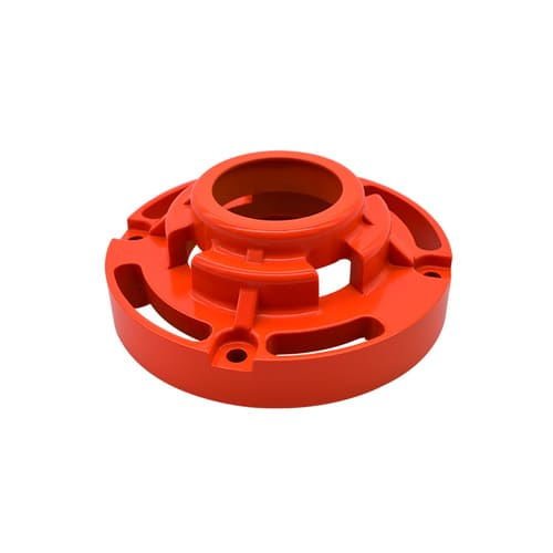
Bosses are projecting elements found in cast items that are typically used as mounting points or standoffs. Bosses might be incorporated into your design to prevent the requirement for boring, time-consuming activities as a secondary process.
Bosses must be created to maintain a uniform wall thickness compared to the surrounding component since significant changes in wall thickness can result in excessive shrinkage and sinking that negatively affect a part’s appearance and even its integrity. Adding a hole to the center of the boss is a standard technique for maintaining equal wall thickness.
Ribs
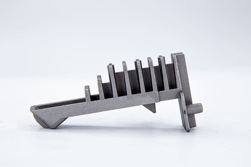
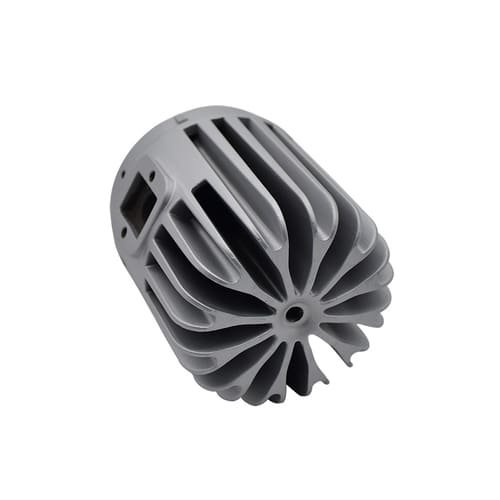
Small bridges of material called ribs can be inserted between walls to strengthen them without using an excessive amount of metal. They also increase the number of flow channels accessible, which makes it easier for molten metal to reach every area of the die.

Ribs are typically introduced to a design in odd numbers or offset from one another in order to prevent stresses from affecting adjacent ribs.
Undercuts
In the manufacturing industry, undercuts refer to recess surfaces that are inaccessible to straight tools. Since undercuts have the potential to keep the die from “gripping” the cast product and preventing die separation during solidification, careful design is required.
You can create your parting line around an undercut if it is important to your design. Another option is to use semi-permanent molds or dies that have more components than just the core and cavity.
Holes and Windows
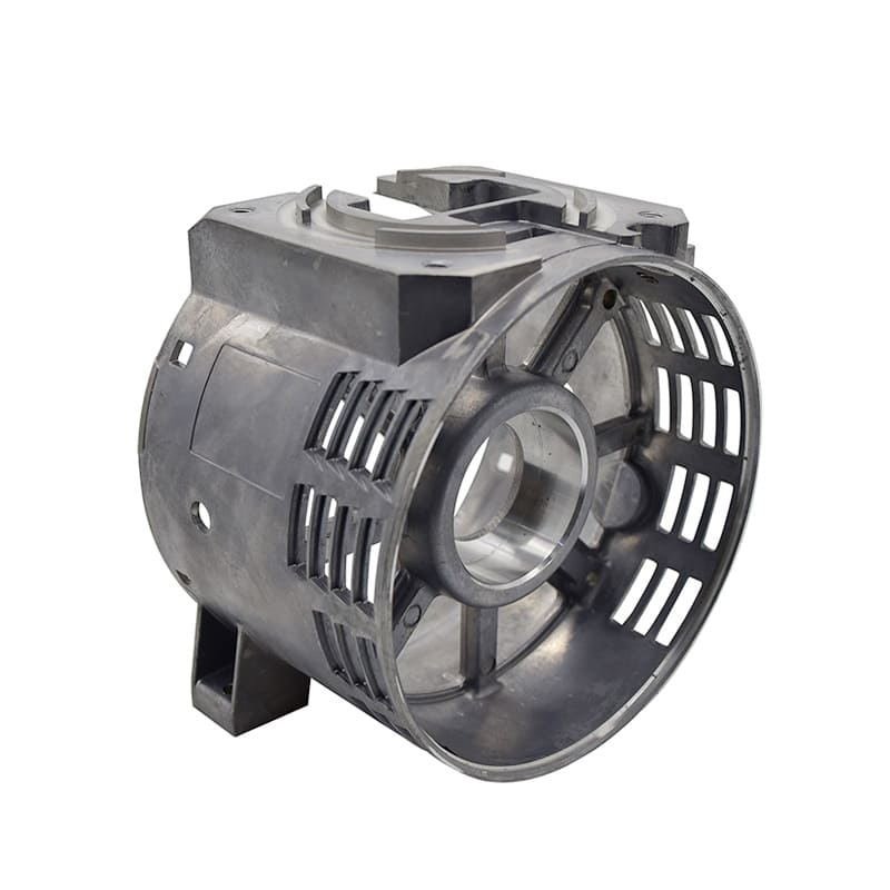
Accounting for the holes and windows necessary in a final die-cast product during the design process can greatly reduce the total amount of post-molding machining needed. Manufacturing times can be greatly reduced by carefully considering drilling, milling, and other machining operations and eliminating or minimizing them whenever possible.
The additional advantage of holes and windows is that they often don’t create too many new design issues. This problem can be reduced by rounding off any edges on holes and windows with fillets and radii.
Conclusion
You may improve the efficiency of die casting by changing your part design to take advantage of the process, which can also better meet your company’s needs.
The design stage is the first step in any production process, including aluminum casting. We believe that after reading this aluminum die-casting design guide, you already have a firm understanding of the crucial elements involved in creating aluminum parts. I hope this will enable you to create a superior product.

