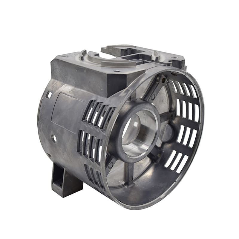
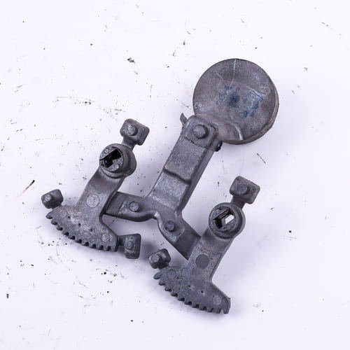
Aluminum die cast tooling plays an important role in die casting’s efficiency and precision. It is a common industrial process widely used to create complex metal parts with excellent accuracy.
Similarly, die cast tool design is crucial in both the final product’s quality and the process’s overall productivity.
In this article, we will provide you with an in-depth explanation of:
- Die Casting Tooling
- Ia tool and die cast
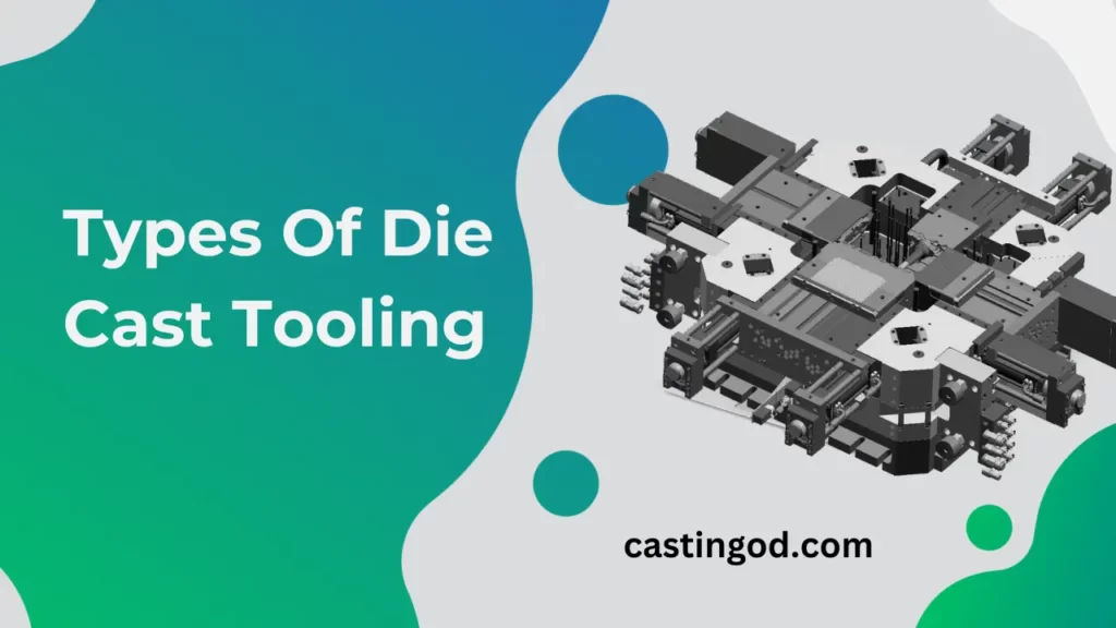
- Types of Die Casting Tooling
- Maintaining and Troubleshooting Die Casting Tooling
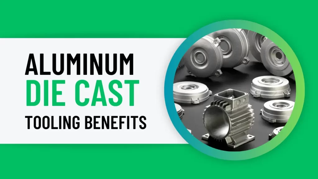
Top 5 Aluminum Die cast Tooling Benefits
| No. | Important Point | Description |
| 1 | Durability and Hardness | Aluminum die cast tooling is known for its exceptional durability and hardness, making it ideal for producing high-quality castings with consistent dimensions and smooth surfaces. |
| 2 | Dimensional Accuracy | Aluminum die cast tooling can achieve high levels of dimensional accuracy, ensuring that castings meet the precise specifications required for their intended applications. |
| 3 | Versatility | Aluminum die cast tooling can be used to produce a wide variety of shapes and sizes of castings, making it a versatile tool for manufacturers. |
| 4 | Cost-Effectiveness | Aluminum die cast tooling can be a cost-effective solution for producing large quantities of castings, especially compared to other casting methods. |
| 5 | Longevity | Aluminum die cast tooling can last for a long time, even with heavy use, making it a worthwhile investment for manufacturers. |
7 Components of Die Casting Tooling
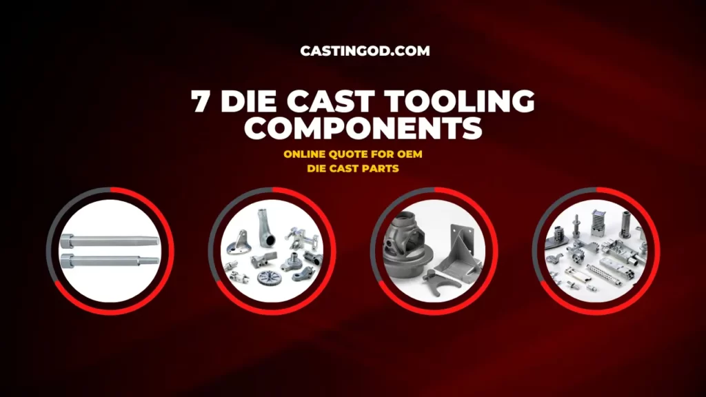
Die-casting performance depends mostly on effective tools. Thus, it’s important that both the customer and the die-caster know their skills and how they relate to project requirements.
The terms and components of dies that are used regularly are:
- Ejector plates,
- Ejector pins,
- Slides or slide cores,
- Cavities,
- Parting lines,
- Cores or core pins,
- Slides.
Below is a brief overview of some of them:
Cavity Inserts or Cavity Blocks
These are the parts of the die casting where the geometry of the part is produced. These two cavities are the cover and the ejector cavities. The premium-grade tool steel used to make the cavity blocks is heat-treated to an extremely high hardness before being coated for lubrication and extended life.
Parting Lines
The part is made by injecting metal into the cavity blocks and cooling them once the two die halves close. The “parting line” is a line that develops at the point of joining the cover and ejector halves.
Cores or Core Pins
A “core” is a unique and removable die part that forms an interior component of the casting. A core can have any form, but the most popular is circular. A core can be attached to the die chamber or a slide, and it can be moved by a hydraulic cylinder, a mechanical die opening and closing mechanism, or another method.
Slides or Slide Cores
A slide, commonly referred to as a slide core, is the section of the die. It develops a feature of the casting and must move at an angle to the parting line in order to be created. This arrangement cannot be made with the die opening and closing as usual.
The phrase “slider core” refers to either a pin inside the larger slide mechanism or an ordinary core pin that is placed in and out at an angle to the parting line.
Hydraulic Cylinders and Angle Pins
Slides are most commonly operated by angle pins and hydraulic cylinders. To avoid getting in the path of part ejection or removal, both sources of motion must be designed into the tooling.
Ejector Plates and Ejector Pins
The halves reveal the cast part after it has been cast and cooled. Usually, the part shrinks as it cools and remains in the die’s ejector half. The casting is pulled out of the die by using ejector pins that operate on a sliding ejector plate.
The ejector pin creates a faint trace on the casting, indicating that the pin should be placed in a non-cosmetic surface area that is not important to the design. In the end, the size, shape, and other specifications of the part define the quantity, placement, and dimensions of the pins.
Types of Die Casting Tooling
Die casting is a useful technique for precisely casting parts. Die casters use several types of dies to cast a wide range of parts with different features. Below are some of the different types of dies that are used in the die-casting process.
A Single Cavity Dies
A die-casting machine that can only handle single-cavity dies or that doesn’t need multiple-cavity dies is said to be using a single-cavity die. It is a mold with only one cavity that can only manufacture one product every cycle.
Additionally, the one-chambered die lacks slides, which are elements in the die that enable the casting part to be developed with undercuts. Ultimately, it lowers the demand for additional processes and processing costs.
Multiple Cavity Dies
These dies will have multiple cavities. Each cavity provides a set of identical parts. These dies are useful for high volume production. Die casting manufacturers use the die-casting machine which is capable of handling dies with several cavities. Similarly, we can reduce the initial die cast parts cost with multiple cavity dies.
Unit Dies
Unit dies are small, separate dies that fit into a master holding die. The master die usually has a fixed member, although different unit dies can be used to create various parts. Most of the unit dies will be single cavity dies with cover halves and an ejector.
A Cold Chamber Dies
Cold chamber dies are used to make reusable metal dies from cold metal. In fact, the term “cold chamber die-casting” reflects the heating of the molten metal during the process.
The metal is heated in a separate furnace using cold chamber dies prior to being fed into the casting process. The molten metal is forced into the mold, where it starts to take on its final shape, by a pressurized plunger in a separate furnace.
The effective use of cold chamber die-casting is limited to copper, magnesium, and aluminum. Due to their comparatively higher melting points, these metals must melt completely before being pushed into the chamber.
A Hot Chamber Dies
This integrated furnace helps melts metal and pushes the molten metal into the die with the use of a hydraulic piston. Here, molten will take as little as 15 to 20 minutes to form into its final shape.
Maintaining and Troubleshooting Die Casting Tooling
If a die-casting machine is at risk of failure, the operator needs to pay special attention to it, carefully analyze the location of the fault and its potential reason, and choose a sensible maintenance strategy.
Regular die-casting mold maintenance can help minimize premature deterioration. Additionally, it can be helpful to identify any problems before they develop into more serious ones.
Here are some important guidelines for keeping die-casting tooling in good condition:
- Regularly clean the mold: Cleaning the mold is vital for removing any dirt or pollutants that may have formed on its surface. It can help minimize damage such as rusting.
- Lubricate the mold: Proper mold operation depends on the use of lubrication. Additionally, it helps reduce friction, which can harm the mold.
- Check the mold on a regular basis: Checking the mold regularly helps in spotting any wear and tear. This can facilitate quick fixes and prevent more serious issues.
- Keep the mold properly: To avoid deterioration from being exposed to the environment and other conditions, the mold must be stored correctly.
Troubleshooting Common Defects in Die Casting Tooling
Gas Porosity
In casting, gas is trapped by the metal, resulting in gas porosity. Bubbles appear when the casting cools and hardens because the metal’s solid state is less capable of containing gas than its liquid state. These bubbles appear as spherical, round holes or cavities on a casting.
Causes and Prevention
• Use proper fluxing and melting procedures: heat metal in a state of vacuum, with gases with low solubility, or with a flux that prevents the metal from coming into contact with the air.
• Increase sand’s gas permeability: Sand that is coarser has a higher permeability
• Make cores and mold more permeable: Let gas and air escape the mold cavity.
• Before using, dry molds and cores and store them in a dry place.
Hot Tears and Cracks
Cracks develop as a branching pattern of irregular crevices. While some cracks are easy to spot, others may need to be seen with magnification.
At the very end of solidification, when the mold cools, cracks start to develop.
Causes and Prevention
- Hot tears will occur if the metal that is solidifying is not sufficiently solid to endure tensile stresses during the solidification process.
- Poor mold design is the main cause of hot tears.
- Enhancing the mold’s collapsibility can easily fix these issues.
Burrs, Fin, and Flash
One of the most common casting defects is flash. Flash is any extra or unwanted substance that gets cast; it’s also referred to as burrs or casting fin. Usually, at the dividing faces, a thin sheet of metal appears.
Causes and Prevention
- The cause of the flash is a gap or crack on the core surface.
- A gap can result from poorly clamping the flask or from placing enough weight on the mold.
- Reassemble the mold and cores to fix this issue.
Conclusion

Metal die-cast tooling is changing because of advances in automation, material science, data analysis, and technology. In conclusion, the key objectives of the most recent developments and trends in die-cast tooling are cost, quality, and performance.

