Introduction
The mold is an indispensable tooling in casting. You need it for all types of casting, including die-casting, centrifugal casting, investment casting, vacuum die-casting, sand casting, etc.
Also, you need mold for your casting, whether you are using aluminium, zinc, magnesium, brass, cast iron, or any type of metal or plastic.
In this article, we would be discussing mold, mold design, and the features of a mold design. Follow closely.
What is a mold?
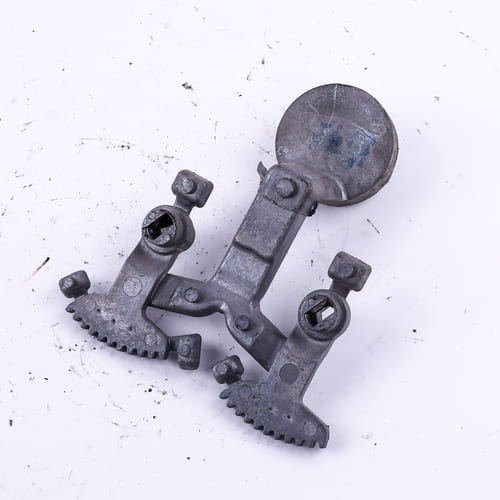
A mold refers to a matrix or cavity in which you pour the molten metal to make cast parts have the desired shape or design.
When you pour molten metal into the mold under high pressure, the metal would shrink inside the mold and grip its core after solidification. Upon solidification, the cast parts would take the shape of the mold.

The mold determines the shape, quality, uniformity, configuration, contours, and dimensions of the castings.
On the other hand, what determines the shape of a mold is the model or pattern. A model is any dimensional object whose shape you want to reproduce with the mold, and ultimately with the casting.
Depending on the quality of the material used in mold preparation, you can use a mold repeatedly in about 5,000-10,000 production cycles.
An overview of mold design
As noted earlier, mold design determines the shape of the casting. So, you need to ensure that the shape of the mold aligns with the dimensions and geometry of the casting you want to make with the mold.
Calculate the mold design according to the size of the casting.
Generally, you can manufacture a mold with metal, wood, or plastic. However, use a material with higher strength and melting temperature than the material you want to cast.
Otherwise, the mold can get damaged. This is why you should use strong metals for die-casting.
Mold requires careful part design. The more complex the casting design, the more complex the mold design. Use 3D CAD/CAM systems for mold design.
The 3D CAD/CAM system is a computer-aided simulation device that helps to optimally adapt mold to cast parts.
To improve the mold’s surface appearance, avoid designing the mold on flat surfaces.
Similarly, there are some other factors that determine the quality of mold part design. Such as:
1: Cast Component
2: metals flow
3: Uniform Wall Thickness
Features of a mold design
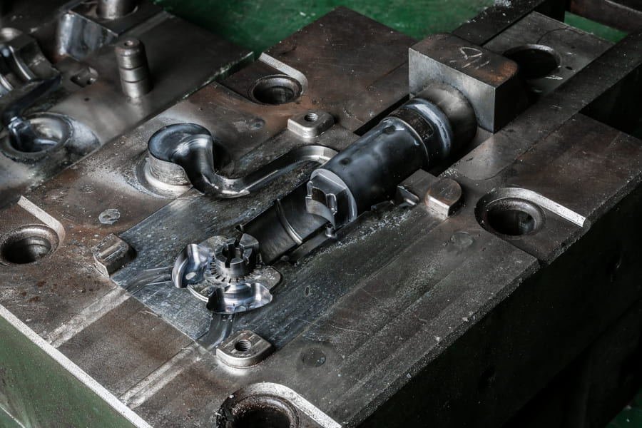
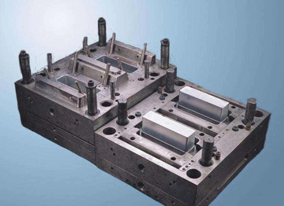
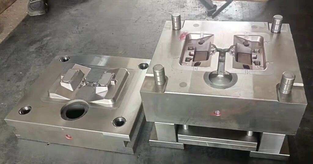
Cavity: The mold consists of two halves. The first half is known as the cavity. It constitutes the external shape of the casting. It is the part of the mold that the molten metal fills to form the desired shape.
Once the cavity is filled, pressure is maintained to compensate for material shrinkage. This gives shape to the cast parts.
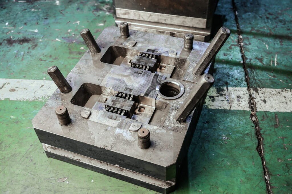
A mold can either be a single cavity or multi-cavity. Multi-cavity molds are mostly used for bulk castings.
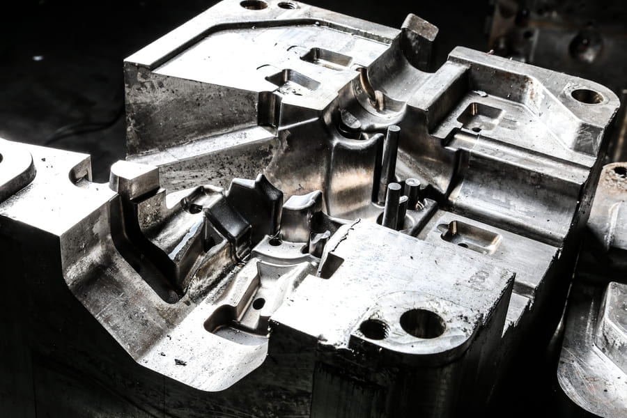
Core: The second half of the mold is the core. It is a preformed, bonded, sand insert placed into the mold to shape the interior of cast parts.
Cores are used to create more complexity in the casting designs. They create holes or chambers in the casting.
The core is mainly made with the refractory. The refractory can either be synthetic or natural sand. To mold cores, use separate core boxes.
Ensure the core has sufficient thickness, and it is free of overhanging or fragile projections.
There are different types of cores. These are the vertical, horizontal, drop, balanced, and cover cores.
The ejector pins: Ejector pins help to remove the casting from the mold. They are located on the core side of a mold. They push the castings out of the mold.
There are different types of ejection pins. These include the case hardened, black, and thought-hand ejector pins.
The case hardened ejector pins are harder pins. They can withstand temperatures above 200°c.
The black ejector pins are coated with a black surface treatment.
They can withstand up to 1000°c. The thought-hand ejector pins can withstand temperatures up to 200°c. They are suitable for plastic injection.
Sprue: This directs the molten metal to the runner. It provides enough pressure to make the liquid metal overcome flow resistance under gravity.
The common sprue shapes include column shape with equal section, big top and small bottom, small top and big bottom, etc.
Runner: This is a machined groove located between the sprue and the gate. It is the channel in the mold which allows the flow of molten metal into the gate.
The sprue directs the molten metal to the runner, and the runner leads the metals flow into the gate. The molten metal would then finally enter the mold cavity.
There are two types of runners: the hot runner and the cold runner. The hot runner molds contain plastics that are heated through a manifold system.
They have heating rings and rods, and keep the material molten till it flows into the cavity. Conversely, the cold runner molds consist of unheated channels.
Gate: This is the small area between the runner and the mold cavity. It is the opening in the mold through which the molten metal gets into the mold cavity.
Depending on the material and casting, the gates can be in different parts around the mold cavity. It should have a thickness of almost two-thirds of the wall size.
To avoid build-ups of materials in the cavity, the gate size should not be too small.
Lifter
Without the lifter, it would be difficult to remove castings without undercuts. Because the lifter can move up and down, it propels the die cast upwards. This helps for seamless ejection of cast parts.
The lifter usually has a head bigger than 1.0m. This is to prevent pressure from moving the angle lifter during the injection molding process. The top of the lifter should be 0.3-0.5 mm higher than the cast part profile surface.
The lifter should have a minimum of 3 degrees shut off. The shut off guides the design of the holes, shits, and other undercut features.
It should have enough clearance to move the hole. Also, design the travel angle not to be more than 11 degrees. You can apply changer to the corners of the mold core head.
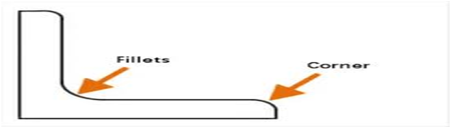
Fillets: Avoid sharp corners or angles in your mold. This is especially for places where there is a rapid change in the cross-section of the design. Where two surfaces should come at a sharp angle, you can use fillets to create a curved part.
A fillet is a sharp-edge breaking feature that adds a radius, either concave or convex, to the interior of a mold.
It is a junction you can use to shape the mold and smoothen an angled surface. You can use it to avoid any undesired corners in the casting
Fillets remove cracks and tears at the re-entry angle. It prevents high-strength concentration and reduces heat concentration on the mold and cast parts.
You can use it in any part of the mold, except in the parting line. Avoid increasing the size of the fillet. Else, this can cause shrinkage porosity in the mold.
Drafts: This is the degree of taper of a side wall or the angle of clearance. Note that taper means the difference in diameter of the top band bottom of a casting.
The draft is determined by the mold’s geometry, manufacturing capabilities, shrink rate, wall depth, etc. It prevents the cast parts from being parallel to the motion of the mold opening. It enhances seamless removal of cast parts.
You should incorporate the draft, right from the prototype to the design stage.
By this, you won’t need to re-design the mold to accommodate the drafting process.

In designing the draft, ensure the cavities on the deep pockets have steeper draft angles. This would prevent vacuum and friction forces during ejection.
Take note of the texture of the casting. Light textures need a 1-5 degree draft, while complex textures like leather need a 5-12+ degree draft. Ensure you apply drafts to all the vertical faces. Always draft both the cavity and core sides of the mold.
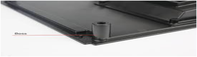
Bosses: These are knobs that serve as mounting points or stand-offs in mold design. They create points at which assembled products can be fastened together.
Before the manufacturing process, determine its hole size. Preferably, you can move the boss inwards, and not near exterior walls. Ensure the boss is not undersized, as such boss may not retain the installed fastener.
Also, ensure the boss is not oversized, as this can cause sink marks on opposing walls of the injection molded parts.
Be sure the thickness of the boss is less than the thickness of the casting. Preferably, the boss should not have more than 60% of the nominal wall thickness.
However, if the boss is in a hidden place on the mold, you can have a thicker wall. This is to allow increased stress caused by self-tapping screws. Also, the height of a boss should be less than 3 times the outer diameter. This is because tall bosses can generate thick sections and material mass at the base.
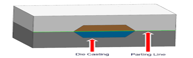
• Parting line: This is the dividing line that splits the core and the cavity halves of a mold. It determines the direction of a mold opening. It is in a perpendicular direction from the mold opening direction.
In designing the parting line, determine the opening direction of the mold relative to the cast part. Always draft the walls of the injection molded parts away from the parting line. Avoid a side parting line.
Properly seal the parting lines. Otherwise, the mold would leak over the parting line during the secondary operation of molding process.
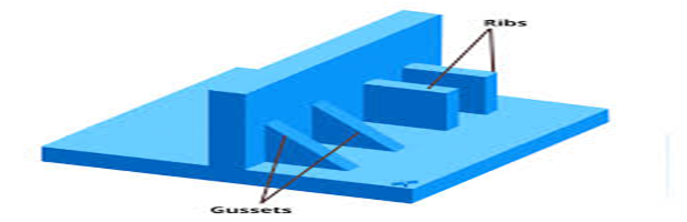
• Ribs: Ribs are thin extensions that run perpendicular to a wall. They are wall-like, thin features designed into the geometry of a mold. They are used to replace thick wall sections to avoid warps, voids, sink marks, etc.
To prevent stress from adjacent ribs, use the ribs in odd numbers. Preferably, the rib height should not exceed 3 times the primary wall’s thickness.
Avoid using taller ribs. Although taller ribs can offer support to the mold, they can cause serious defects in the casting if improperly sized. Preferably, the rib’s weight should not exceed 50-60% of the primary wall thickness.
Also, avoid using thick ribs. Thick ribs can result in serious problems to the cast parts. This is because the point where a thick rib is attached to the primary wall would also be thick and may lead to defects like sink marks, warps, voids, etc.
Thick ribs, due to concentrated stress, can affect the casting’s strength. To prevent concentrated stress in the mold, round the base with a radius. The radius should not exceed 0.5 times the width of the primary wall’s thickness.
Conclusion
In this article, we considered the concept of a mold, an overview of mold design considerations, and the features of a mold design. In mold making, use a material with higher strength and melting temperature than the material you want to cast.
The various features of a mold design include cavity, core, ejector spins, sprue, runner, gate, lifter, fillets, drafts, etc.